Our solutions and developments
D'Elite VisionGuard
Innovative products and technologies for investors and partners
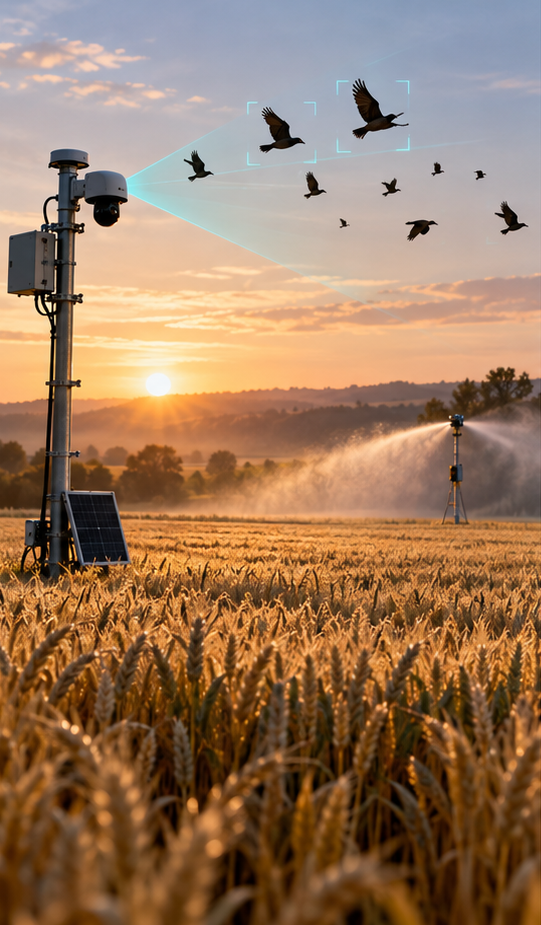
Conceptual visualization
Perception as the first step to action
D'Elite VisionGuard is a computer vision software module for detecting target objects, estimating their position, and transmitting the result to an external application or robotic platform.
The system is designed around local image processing, interchangeable detection models, and multiple operating modes: stereo, single camera with sensor degradation, and additional NV/thermal sources.
1
One module - different practical scenarios
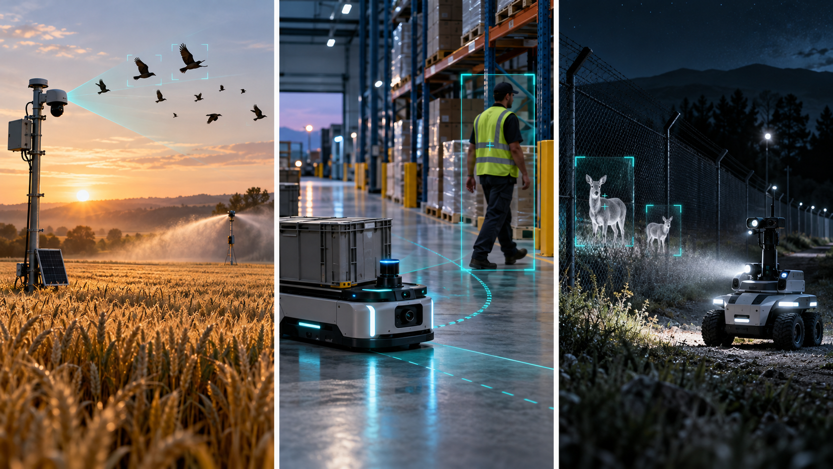
Agricultural sector
Detection of birds near crops and deployment of selected non-violent repellents.
Detection of birds near crops and deployment of selected non-violent repellents.
Mobile robotics
Transmitting coordinates and events to the robot to check an area, avoid an obstacle, or continue the mission.
Transmitting coordinates and events to the robot to check an area, avoid an obstacle, or continue the mission.
Night monitoring
Ability to connect an NV camera, thermal imager, and IR trigger for low-light scenarios.
Ability to connect an NV camera, thermal imager, and IR trigger for low-light scenarios.
2
How does the processing take place?
- The cameras transmit images with timestamps.
- The model finds objects of the selected class and selects the target object.
- A stereo pair estimates coordinates; with a single camera, an explicitly labeled mono result is returned.
- The result and status of the sensors are available to the operator or the autonomous circuit.
Prototype validation
What has already been proven in a real run
The technical risk for the perception core has already been mitigated: distance accuracy, correct target selection, and safe failure upon video loss—basic requirements for a pilot in field scenarios—have been confirmed using a live camera.
For the investor
The detection and position estimation core is already running on hardware. Further investments are being made in stereo calibration, target models, and integration with the Autonomy Layer—not in trying to figure out if it works at all.
Correctness without purpose
If the object leaves the frame, the system returns "no target", maintains the operating mode and does not go into a false safe-idle mode - fewer false stops in the pilot.
3
Sensors enhance different parts of the system
Stereo RGB
Two calibrated cameras provide a basis for triangulation and coordinates in a common system.
Two calibrated cameras provide a basis for triangulation and coordinates in a common system.
NV and thermal imager
Additional images can improve observation in twilight and dark conditions.
Additional images can improve observation in twilight and dark conditions.
IR sensor
Serves as a presence or movement trigger and helps avoid running a full analysis unnecessarily.
Serves as a presence or movement trigger and helps avoid running a full analysis unnecessarily.
Laser rangefinder
Can specify the distance to the object at which the beam is aimed.
Can specify the distance to the object at which the beam is aimed.
Sensor logic support is provided in the software core. Hardware adapters and field testing of additional sensors are performed separately.
4
Connecting with the Autonomy Layer
VisionGuard reports what the system sees. The Autonomy Layer decides how to carry out the mission.
The intended connection: target coordinates and sensor status are fed to the robotic circuit, which initiates the mission step, records events, and implements a failure recovery policy.
The ROS 2 bridge and the Autonomy Layer simulation framework are separate. Integration with VisionGuard and the physics platform is not yet complete.
5
Implementation phases
Phase 1Prototype and basic validationCurrent
Current status: mono-detector, coordinate estimation, and camera loss processing; confirmed largest target selection and distance error of approximately ±10 cm at the target distance. Stereo pair calibration and coordinate measurement on the test bench.
Phase 2Target models and sensory circuit
Configuring interchangeable models for selected object classes, assessing detection quality, and connecting additional sensors according to a scenario.
Phase 3Integration pilot
Transfer coordinates and events to the Autonomy Layer, test the mission in simulation and then on the selected robotic platform.
Phase 4Field testing and scaling
Verify accuracy and robustness in the target environment, prepare repeatable implementation for new sites and equipment types.
Current stage
Prototype and testable roadmap
Phase 1
The working mono prototype has passed basic coordinate, target selection, and camera loss recovery checks. The next step in Phase 1 is a calibrated stereo prototype with reproducible accuracy measurements.
We invite platforms and partners to test applied computer vision and robotics scenarios.
Discuss the pilot